
DESIGN AND CONSTRUCTION OF A PORTABLE MOVABLE CRANE
INTRODUCTION
Background Study
A movable crane is a machine that is capable of raising and lowering heavy objects and moving them horizontally. Movable cranes are distinguished from hoists, which can lift objects but that cannot move them sideways. Movable cranes are also distinguished from conveyors that lift and move bulk materials, such as grain and coal, in a continuous process.
The word crane is taken from the fact that these machines have a shape similar to that of the tall, long-necked bird of the same name. Human beings have used a wide variety of devices to lift heavy objects since ancient times. One of the earliest versions of the movable crane to be developed was the shaduf, first used to move water in Egypt about four thousand years ago. The shaduf consists of a long, pivoting beam balanced on a vertical support. A heavyweight is attached to one end of the beam and a bucket to the other.
The user pulls the bucket down to the water supply, fills it, and then allows the weight to pull the bucket up. The beam is then rotated to the desired position and the bucket is emptied. The shaduf is still used in rural areas of Egypt and India. As early as the first century, the movable crane was built that was powered by human beings or animals operating a treadmill or large wheel.
These early movable cranes consisted of a long wooden beam, known as a boom, connected to a rotating base. The wheel or treadmill powered a drum, around which a rope was wound. The rope was connected to a pulley at the top of the boom and to a hook that lifted the weight.
An important development in movable crane design occurred during the middle ages when a horizontal arm known as a jib was added to the boom. The jib was attached to the boom in a way that allowed it to pivot, allowing for an increased range of motion. By the sixteenth century, movable cranes were built with two treadmills, one on each side of a rotating housing containing the boom.
Movable crane continued to rely on human or animal power until the middle of the nineteenth century when steam engines were developed. By the end of the nineteenth century, internal combustion engines and electric motors were used to power movable crane. By this time, steel rather than wood was used to build most cranes… (Scroll down for the link to get the Complete Chapter One to Five Project Material)
Research Objectives
The objective of this project is categorized into general and specific objectives:
- General objectives: The general objective of the research project is to design and produce portable and moveable lifting crane to lift heavy loads that are beyond the capacity of human beings applying only small force in the production machine shop.
- Specific objectives: The details of the objectives of the research project are listed as follows: (Scroll down for the link to get the Complete Chapter One to Five Project Material)
Statement of the Problem
Nigeria’s aspiration to be among the world’s first twenty industrialized nation by the year 2020 may not be met unless adequate and endogenous workshop equipment is deployed to supplement imported ones in all its maintenance and production shops. Available data from the Nigeria Ports Authority shows that about 900,000 vehicles were imported into the country between 1992 and 2003.
This figure has increased geometrically in the last ten years. According to the Nigeria Auto-Industry Quarterly Update 2012, the country has an annual demand of 300,000 new vehicles (Business Monitor International, 2013). Repair and maintenance of these vehicles are regular and must take place for their continued operation.
This informs the reason for the ever-increasing number of such automobile repair shops in the country. Most shops, however, are grossly unequipped for proper handling and job execution in the shops. Sound professional best practice aimed at workshops injury and accident prevention and reduction ensure the utilization of appropriate tools for any job.
Motor vehicle repair and maintenance often require the lifting of the entire vehicle or sub-assembly part of it or the lifting up and down of its heavy components. Also in other industries and welding shops, there are items and repairs which need the employment of shop cranes.
The lack of shop crane utilization in our industries and automobile repair shops not only leads to injury and accident but also to poor repair and maintenance occurrence… (Scroll down for the link to get the Complete Chapter One to Five Project Material)
![]()

LITERATURE REVIEW
Background History of Crane Evolution
This literature review revealed the movable crane selection and most of the work has been conducted using knowledge-based systems to select the most appropriate movable crane for building. Shapira and Glasscock (1996) have described the culture of using mobile and tower movable crane for building construction. They demonstrated project characteristics and compared tower cranes and mobiles movable crane to select the favored alternative.
They further found that the selection of cranes for a project is affected not only by project-specific considerations but also by prevailing external conditions that often are the cumulative effect of the characteristics of a whole project population. Movable crane use and evolution started with the needs in the erection of anvil and structural works. Traveling cranes of the hand-operated type were in use in the 1880s.
About this time complicated designs of powered motion were offered by English and American builders involving a driving shaft along the runway and multiple clutches for transferring the power of the driving shaft to the hoist, trolley, or bridge motions.
Successive crane development ran thus: 1880 saw the hand-powered movable crane, 1900 the electrically driven movable crane with a motor for each motion; by 1920 definite standards had been established for a movable crane in general and for various types of services; 1940 brought the enclosed gear cases, roller bearings, and standardized designs; and 1960 produced the changes in crane control which resulted in smoother operation, safer handling of the load, remote operation and new safety features for protection of equipment and personnel (Greiner, 1967).
From the cranes used in building and structural engineering works, movable cranes have been developed for all cadre of material handling jobs in the manufacturing and service industries. As a result, many different varieties of crane exist. Broughton (1958) grouped all cranes into four main categories, which remain applicable today, as enunciated by Thompson Geoffrey (2007):
Overhead Travelling Crane: This consists of fixed rails lying on one or two elevated girders with the trolley or crane bridge (with hoisting apparatus) that can transverse the length of the rails.
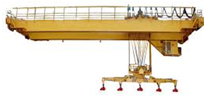

Fig 2.1 Overhead Travelling Crane
The Jib Crane: This consists of an inclined member that can rotate about a central point and suspend the load from the outer end of the inclined member.
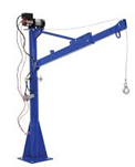

Fig. 2.2 The Jib Crane
Gantry Crane: This is a girder or girders connected to vertical members which are either fixed or move along tracks at the base of the vertical member, the hoisting equipment can usually traverse the bridge girder or girders.
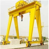

Fig 2.3 Gantry Crane
Cantilever or Tower: This is a vertical mast with a horizontal cantilever that rotates horizontally around the vertical member. The trolley and hoisting equipment moves along the… (Scroll down for the link to get the Complete Chapter One to Five Project Material)
METHODOLOGY
Design Work
The designing work was carried out using Pro E software. The required dimensions of the driver and the driven wheels were taken as per the design equations. Pro E is the most widely used design software which helps in designing 2 as well as 3-dimensional models using simplified alphabetical and numerical commands. Both the driving and the driven wheels were drawn to the required dimensions using the circle command. A slot was cut on the Geneva wheel using the trim tool. It was then edited using poly-line command and the remaining slots were constructed using the array tool. The crankpin and the driving wheel were drawn to the required dimensions.
Design Criteria
There are three major considerations in the design of cranes.
- The crane must be able to lift the weight of the load;
- The crane must not topple;
- The crane must not rupture.
Lifting Capacity
The lifting capacity of hydraulic crane mainly depends on the following:
- The lever: A balance crane contains a horizontal beam (the lever) pivoted about a point called the fulcrum. The principle of the lever allows a heavy load attached to the shorter end of the beam to be lifted by a smaller force applied in the opposite direction to the longer end of the beam. The ratio of the load’s weight to the applied force is equal to the ratio of the lengths of the longer arm and the shorter arm and is called the mechanical advantage.
- The Pulley: A jib crane contains a tilted strut (the jib) that supports a fixed pulley block. Cables are wrapped multiple times around the fixed block and round another block attached to the load. When the free end of the cable is pulled by hand or by a winding machine, the pulley system delivers a force to the load that is equal to the applied force multiplied by the number of lengths of cable passing between the two blocks. This number is a mechanical advantage.
Design & Fabrication of Hydraulic Floor Crane 2014 Trinity Institute of Technology & Research, Bhopal | Department of Mechanical engineering Page 14… (Scroll down for the link to get the Complete Chapter One to Five Project Material)
RESEARCH FINDINGS AND ANALYSIS
Table 4.1 Specifications of the Project
|
Name |
Material |
Dimensions |
||||
|
1 |
Pulley | Fiber |
Outer Diameter – 3.81 cm Inner Diameter – .8cm Length – 5 cm |
||||
|
2 |
Horizontal Arm | Mild Steel
|
Length – 55.88 cm Width – 5.08 cm Thickness- 2cm |
||||
|
3 |
Vertical Arm | Mild Steel
|
Length – 100 cm Diameter – 15.24 cm |
||||
|
4 |
Ball Bearing | Stainless Steel | 6400 | ||||
| 5 | Wheels | High Steel |
7cm |
||||
|
6 |
Handle | Mild Steel
|
Length – 38.1 cm Diameter – 1.9 cm |
||||
|
7 |
Base | Mild Steel
|
Width – 60.96 cm Length – 91.44 cm Thickness – 5.08 cm |
||||
|
8 |
Hydraulic Jack |
3 tons |
|||||
|
9 |
Wire | High Steel |
200cm |
||||
|
10 |
Jack Holder | Mild Steel |
Length – 12.7cm Width – 12.7cm |
- Design of vertical column
The vertical column is modeled as a strut or short compression member thus it is exposed to compressive stress and this stress is the sum of simple stress component and flexural (bending) components
Figure 4.1 Vertical column
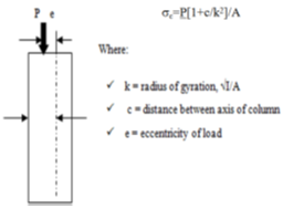

Therefore: c=0.15m/2, e=1.6m
The column cross-section subjected to compression stress is
Figure 4.2 Cross Section of Vertical Column
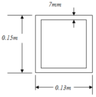

The area of the column cross-section is
= [0.15*0.13) − (0.116*0.136)]m2 = 3.724*10−3 m2
Moment of Inertia
Ixx = ( 0.15*0.13)3 − (0.136*0.116)3 /12
(2.74625 −1.769)*10−5 m4
Ixx = 0.97725*10−5 m4
Iyy = (0.13*0.15)3 − (0.116*0.136)3 *10−5 /12
Iyy = 1.22089*10−5 m4
NOTE: Buckling always occurs about the axis having a minimum radius of gyration or least moment of inertia, therefore in our case buckling occurs along the horizontal direction (Ixx)… (Scroll down for the link to get the Complete Chapter One to Five Project Material)
SUMMARY OF FINDINGS, CONCLUSION, AND RECOMMENDATION
Results
After a successful fabrication of the machine, it is imperative to test or evaluate the machine’s performance. Hence, the test was conducted as follows;
(i) Selection of standard loads to be lifted (1000N, 2000N, 3000N, etc.)
(ii) Hook the selected load to the arm of the movable crane
(iii) Lock the control valve… (Scroll down for the link to get the Complete Chapter One to Five Project Material)
Conclusion
In this research work, critical study and analysis of the working principle of a hydraulic movable crane were carried out with a detailed analysis of the machine component. From the study, the design was based on ways of improving safety, weight, ergonomics, aesthetics, cost, and durability.
From the result obtained, it can be concluded that the hydraulic crane will do a lot of good to technicians and maintenance engineers at local automobile and plant repair workshops because it would save the time and energy which might be expended on the crude way of lifting and moving heavy loads within the workshop… (Scroll down for the link to get the Complete Chapter One to Five Project Material)
![]()